| PhD A. Y. Goncharov | |
 | Short note about the author. Born in 1949, a participator of a scientific school of microelectronic energetic systems of academic Y. I. Konev, graduated as PhD at Moscow Aviation Institute. The author had worked for many years in NIIRTA, specializing in aviation and artillery power electronics. Organizer and chief designer of several scientificmanufacturing companies, with Alexander Electric in their names. President of AEPS-GROUP in Prague. |
Distributed power supply matrix systems (DPSMS) [1] are gaining more application due to spreading of not only digital principles of processing signals, but constructive design of blocks for large systems. Matrix technologies are literally quickly evolving in equipment implementation of digital network devices, supercomputers, radars, also televisors, photocameras and in many other devices. In any of these there is a need for power supply units and systems, which are systematically built on matrix principles of design.
The definition of distributed power supply matrix systems – DPSMS – is a combination of identical power supply units (PSU), spread over the plane of a matrix and located in cross-sections of rows and columns of said matrix, connected (usually) between each other by control buses and buses to exchange states information of PSUs.
Let’s look at systemic specifics of DPSMS in example of one of the most important objects of the newest electronics – active phase array radar – APAR [2, 3, 4, 5]. Let’s analyze some perspective solutions for systems of power supply for APAR, specifics of construction and arguable details, that are presented in every newest technical solution in modern life.
Thus, what is APAR from microelectronics perspective?
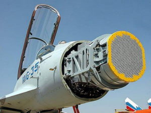
APAR is a combination (canvas) of receiving-transmitting modules (RTM), forming a matrix (not necessarily rectangle) of rows and columns in plane perpendicular to the direction of a radiation beam. The main principle of APAR – is to perform, during signal transmission and reception, a wide-angle scanning of space not by mechanical repositioning of radar, but by phase control of beam of every unit of matrix, of every RTM unit. Since maximal resolution of such radars is directly connected with how high signal frequency is, the matrix grid step is limited to the half-length of transmitted / received wave [2, 6]. As a consequence, considering presently used frequencies (radar wave lengths of tens and units of millimeters), there is a physical limit of maximal linear dimensions of RTM along the plane of APAR antenna grid. Due to this, the field of power electronics for APAR is met with prefixes as Mini, Micro, MicroMini.
The most important feature of APAR – practically equal to unity is the reliability of the whole grid together with equipment located in the grid, combined together as RTM units. To be fair though, the unity reliability applies to isolated and randomly located cases of RTM and antennas failure. The failure of a significant part of the row is still however very unpleasantly critical [2].
Factually all APAR equipment, included in the grid, is covered by the protective “umbrella” of the maximal reliability of the matrix grid!
Another specificity of APAR – is impulse power consumption of the grid.
Based on text above, it’s possible to form main requirements to DPSMS of APAR.
| Range mark | Radiation frequency, GHz | Wave length, mm | max. dimensions ∆ L, mm |
| S | 2 – 4 | 150 -75 | 70 – 33 |
| C | 4 – 8 | 75-37,5 | 33 – 15 |
| X | 8 – 12 | 37,5 – 25 | 15 – 9 |
Table 1: frequency and wave lengths ranges
There are several characteristic types of APAR, in this paper we’ll look at DPSMS of aviation APAR, (located behind nose cone) as the most difficult technical object to construct from the standpoint of system of power supply.
There are basic (in regards to need of power supply) components of RTM [8], that act as a load for PSUs: radio-transmitting unit (RTU), phase shifter, radio-receiving unit (RRU) and microprocessor unit of processing and control (MPCU). Certainly, there is a few more of such units, however those could be included (load type wise) in some of above mentioned units of RTM.
On fig. 1 there is illustrated a construction of RTM, including components of a cooling system (marked with color blue).
![]()
Fig. 1: Receiving-Transmitting module of APAR – RTM
As an example, we shall look at one of the typical power supply tasks, when the biggest load is the RTU. Modern radar transmitters use GaN based output transistors, that achieve much higher efficiency compared to GaAs based [9].
The highest efficiency will be held by PSU with output voltage in range 10-15 V, with use of synchronous rectification, which complicates the construction and relies on presence of high-current circuits in the unit, or with range 27-60 V, which allows to simply the construction, designing PSU without synchronous rectification and using circuits with decreased current values.
All other loads for PSU – RRU, MPCU and rest have significantly lower fraction of power draw compared to RTU, circa not lower than 20 % of the whole load. For their power supply, usually additional voltages are required, for example +5 V, +2,5 V, -5 V. The quantity of additional voltages usually points to professionalism of complex specialists – lower the number of additional voltages one can achieve in one RTM, higher the reliability, simple the construction and better the miniaturization. However, usually there is no need for galvanic isolation of common wires of different RTMs, which allows to design quite compact impulse stabilizers of small voltages, both positive and negative, the smallness of which is ensured by high conversion frequencies, higher than 500 kHz. Definitely, there must be done quite a job by EMC specialists, familiar not only with HF devices, but more so with field of impulse PSUs.
As a consequence, in present, without much effort, in RTM’s part (fig. 1) PSU – it’s possible to design microminiature converter (based on GaN transistors) with galvanic isolation, converting input DC voltage of 27 V or 300 V (stated as reference) to output voltage of 28 V, required by RTU. Main output voltages then allow creation of secondary additional outputs of +5 V, +2,5 V, -5 V for RRU and MPCU.
Exemplary variant of such schematic design is shown on fig. 2.
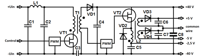
Fig. 2: Simplified quadruple-output schematics of PSU, placed inside a RTM
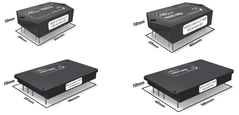
Fig. 3: DC/DC converters in individual cases: TESND20, TESND30, TESND50 and TESND80 with high
power densities in range 3-5 kW/dm3
Profiles of RTM from 15 mm x 15 mm to 24 mm x 24 mm (range C) are well fit with the insides of modified DC/DC PSUs of series TESND20, TESND30, TESND50 and TESND80 with high power densities 3-4 kW/dm3 manufactured by AEPS group [10], specifically designed for solving power supply challenges for APAR equipment. In fig. 3 one can see outside appearance of PSUs in individual cases for wide application range.
Schematics and location possibilities of given PSUs in RTM of APAR allow to create an impulse mode with output power of 30 W, 45 W, 75 W and 120 W, and mode of medium power up to 20 W, 30 W, 50 W and 80 W, respectively. Such power characteristics cover needs of the most aviation tasks for APAR in present and close future perspective. In gives case, exactly this part of power supply system, starting from bus of 27 V or 300 V, is under the protective “umbrella” of maximum reliability of matrix grid of APAR [2, 5]. The power supply system itself (actually being shortened and unfull!) in such case is called decentralized, marking its main flaw – complete irrepairability (about other flaws, declared in [5], the author is ready to richly argue). In case of failure of PSU during technological tests one would have to discard whole quite expensive RTM.
However unfortunately, the victory in microminiaturization of power supply APAR system is quite far. We have yet looked at only one type of constructing “end-part” of system, naturally paying attention to expensive RTM, quantity of which in modern aviation radars with APAR has gone over 2000 pcs. It’s now the time to look at the beginning – at primary onboard power supply.
Most often for primary power supply a 3-phase generator is used, for example 3 x 115 V – 3 x 380 V, 400 Hz or 50 Hz (for heavy objects). To create an intermediate bus of 27 V or 300 V from 3-phase primary power input, AC/DC converter is used ranging in power from several kW to tens of kW. It’s very important to provide more-or-less smooth, without high impulse contents, 3-phase generator load – otherwise energetic efficiency is lost and generator starts overheating. Smooth load is usually ensured by power factor correction (PFC).
In standard case, such AC/DC converter starts with EMC filter, so the noise from after-placed impulse devices can’t get to the primary power circuits and vice versa. After there is PFC and usually a bridge high-frequency inverter, transformer output of which (after filtering) forms mentioned intermediate bus.
This part of power supply system of APAR is strictly centralized and has to fight for its reliability by itself, using only one method left – back system of type N+M.
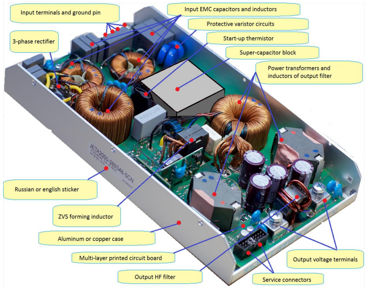
Fig. 4: typical 3-phase converter JETNA2000, without lid
Thus, whole system of power supply of APAR, from output of 3-phase generator to HF part of RTM, is of mixed type – usually such system is called partly-centralized. However for the author of this article it’s more logical to descend from ideal to reality, so let’s move from decentralized system to partlycentralized system of power supply, noticing that the most important advantage of APAR itself – coefficient of practically unity, is denied by unreliability of centralized AC/DC converter. Thus, it’s important to tread carefully when choosing schematics and construction of such device, with minimal loss in reliability.
Most fitting from present selling products are wide-temperature planar 3-phase-input converters of series JETNA1000 – JETNA5000 manufactured by APES-GROUP [10]. This series has unprecedented low profile – unit height of 38 mm with series of output power from 1000 W to 5000 W. Functioning case temperature range can be as wide as -60° to +85° C. Power densities of such converters are higher than 2 kW/dm3. Outside appearance of such unit JETNA2000 and his inside contents are illustrated on fig 4.
To achieve high values of reliability of AC/DC converter, it’s necessary to use parallel connection of sufficiently high number of such devices [5], functioning with load coefficient of no more than 0,7. For example for total power of 4-6 kW it’s typical to use 8-12 pieces of 2000 W converters – JETNA2000, for 16-24 kW of total power, it’s necessary to use 8-12 pieces of 5000 W converters – JETNA5000, and so on.
Ultimate planar design of indicated power supplies helps create high amount of construction variants of centralized AC/DC converter including cooling system.
Despite the flaws of such partly-decentralized system (fig. 5) of power supply of APAR, i.e. decrease of APAR reliability, such systematic and constructive solution can be widely used, if it’s really necessary to have intermediate bus of 27 V or some other voltage, belonging to the typical accumulator voltage series, for example 48 V and such, [11, 12, 13]. Presence of 300 V bus may be justified by tendency to decrease the weight of copper wires in power distribution system of APAR grid. There are tasks, in which several onboard voltage generators are used and it’s necessary to duplicate them – in such cases centralized power supply system “has a right to live”. Finally, simple necessity of conforming to principle of aggregating, when building complicated equipment for landbased radars, for example, is a serious argument when choosing partly-decentralized solution.
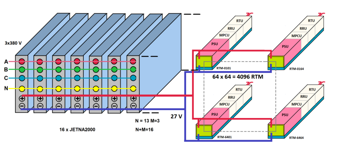
Fig. 5: partly-decentralized system of power supply of APAR
If in radar system there is no accumulator backup or there are no duplicate generators, the necessity of above described centralized AC/DC converter is doubtful. The author believes, that such solution in most cases might significantly worsen mass-dimensional and reliability characteristics of APAR, and the existence of such solution might be explained only by subjective factors, for example by absence of complex approach to design of the whole radar system as whole.
Let’s try to look into alternative way for the case with absence of necessity of accumulators backup or duplicated generators.
The question is – why is there a need to convert AC of 3 x 330 V or 3 x 115 V into DC of 570 V or 170 V, and then once again convert indicated DC voltage into another DC, for example, 300 V. In such setting, there are six high-energetic (and because of that, loss-making heat-wise) conversions: rectification, filtration, conversion by transistor bridge of DC to AC, transforming with inductivemagnetic component (transformer), rectification again and filtration again. At all six stages there are power losses and total efficiency of conversion would be not higher than 92-94 %, which means for 16 kW of output power there’ll be minimum of 1390-1021 W of heat loss.
If that’s the price for having galvanic isolation, which may be necessary to meet a requirement of safety for human and technical equipment, one of the conversions – filtration after first rectification, is clearly redundant, since rectified 3-phase voltage has strong DC content, which suffices for functioning of modern DC/DC converters. The capacitor in such case may be excluded from design, even more so, in AC/DC converters an input filter electrolytic capacitor is a component of increased unreliability, what doesn’t allow an increase in maximal converter function temperature, which would be highly important for increasing efficiency of cooling system.
Further it’s important to understand, that function of galvanic isolation is realized in PSU of RTM, which, if designed properly, allows exclusion of all mentioned conversions except for the first conversion. However, rectifier is a component of increased reliability, which can by principle be just one, and the whole group of backed-up AC/DC modules in centralized part are replaced by one rectifier, fig. 6.
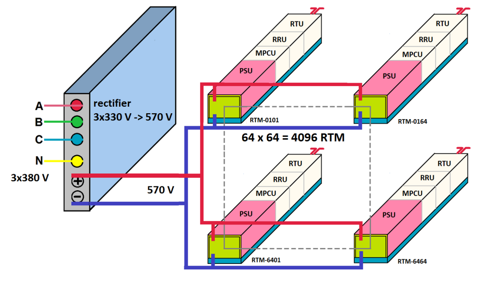
Fig. 6: quasi-decentralized DPSMS
As a result, there is a decrease in weight of centralized AC/DC converter by tens of times and there is a close-to-unity reliability with lighter cooling system. What is lost then? Potential PFC, quite necessary for normal functioning of primary generator, is gone. Nonetheless there is no big tragedy, since exclusion of storage capacitor after rectifier solidly decreases impulse load of generator.
The power supply system for APAR with one rectifier may be called quasi-decentralized.
Finally, there is becoming clearly a new perspective development in DPSMS for APAR, where one rectifier might be broken into many of small rectifiers and include these into RTMs, fig. 7.
The result is excellent – we’ve created a purely decentralized system of power supply for APAR, satisfying all requirements, listed in the beginning of this article.
For this, nothing material and heavy is not to be done, but it’s needed to carry out the most difficult – simultaneously multi-criterially optimize the development of the whole APAR system, integrally, collecting all electronics into RTM, which gets under the protective “umbrella” of the APAR itself.
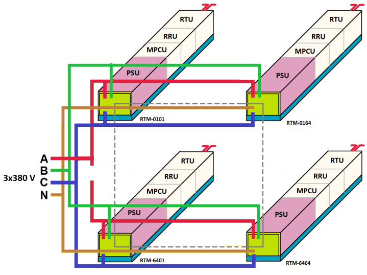
Fig. 7: completely decentralized DPSMS
An eloquent example, how difficulties of miniaturization of DPSMS, with quantity of more than 2000 of RTM, become a slow-down when designing 3D APAR for fighter jet F22 RAPTOR, is shown in information printed in American magazines.
With volume of all AI (airborne interception radar) of 565 dm3 and with weight of 553 kg, with power of DPSMS of APAR of 16 530 W, the volume of DPSMS is 40 % of the total volume, and the weight is 45 %. It’s necessary to note, that in the given case there is used practically centralized system of DPSMS. Such DPSMS possesses critically low reliability and has a big part of the weight of power supply system with its RTM feeders.
Below is shown data to evaluate volumetric, thermal and reliability characteristics of APAR with implementation of all three types of systems, table 2.
For base of calculation were used following values: HF power of one RTM – 8 W; transmitter efficiency – 0,5; signal occurrence – 5 (calculated as 1/D, where D is duty coefficient); efficiency of PSU during impulse time – 0,88; efficiency of PSU during pause – 0,75; power draw of RRU and MPCU – 2 W; quantity of RTM – 4096.
| DPSMS of APAR | Decentralized | Quasi-decentralized | Partly decentralized with back-up |
| Dimensions of RTM with PSU | 24х24х165 mm | 24х24х160 mm | 24х24х160 mm |
| Volume of all 4096 PSU in RTM | 153,9 dm3 | 141,6 dm3 | 141,6 dm3 |
| Volume of centralized part of DPSMS | 0 dm3 | 2,0 dm3 | 23,9 dm3 |
| Volume of whole DPSMS | 153,9 dm3 | 143,6 dm3 | 165,5 dm3 |
| Radar volume without heat exchanger | 390,6 dm3 | 379,6 dm3 | 401,5 dm3 |
| Heat power loss of PSU in RTM | 4366 W | 4185 W | 4185 W |
| Total heat loss of DPSMS | 4366 W | 4608 W | 6191 W |
| Power consumption from generator | 18327 W | 18423 W | 19625 W |
| Reliability coefficient of APAR electronics | 1,0 | 0,996 | 0,991 |
Table 2
The author may cooperate with manufacturers, who would be interested in producing APAR RTMs of new generation with PSUs based on solutions provided in this article.
The list of used literature:

