For MIL-COTS applications, to choose a heat sink for isolated AC-DC converters, it is necessary to determine which thermal resistance is needed for a certain application in the first place.
Thermal resistance (Rt) of a heat sink demonstrates, by how many degrees the temperature of a heat sink will rise in relation to the ambient temperature, provided that the heat sink dissipates a certain heat power. The relation can be represented by such formula:
Rt = (Tof a heat sink – Tamb) / Pdiss = T / Pdiss (1)
| where: | Rt – thermal resistance of a heat sink; |
| Tof a heat sink – temperature of a heat sink; | |
| Tamb – ambient temperature; | |
| Pdiss – power, dissipated by a heat sink into the ambient air; | |
| T – difference between heat sink’s temperature and ambient temperature. |
Heat sink’s temperature is a temperature of its mounting. Depending upon construction (design), heat sinks of different surfaces may have allied thermal resistance showings, and vice versa. Which is why when choosing a heat sink, it is impossible to avoid Rt calculation, and afterwards go on with a heat sink design determination. Rt values are given in the datasheets for heat sinks (heat sink profiles), or can be provided by the manufacturer upon request.
To determine Rt value following formula (1), it is necessary to calculate T = Tof a heat sink -Tamb. As a temperature of a heat sink, you should stipulate the maximum temperature of a heat sink, which must not be exceeded; which is actually tantamount to the maximum case temperature of a power supply, which is mounted onto the heat sink.
For example, for military grade power supplies like JETA 1200 series the breaking case temperature is 85°C, and this is the temperature, which turns on the thermal protection installed in the module. As a maximum breaking case temperature we recommend you to set the level of not more than 75°C (for this example), as along with increase of the case operating temperature, MTBF of the power supply and its elements decreases. With each 10°C of increase in case operating temperature, MTBF dramatically decreases by 1,5…2.
So, if the maximum case operating temperature is set at the level of 75°C, and the maximum ambient temperature is 40°C, then T = 75 – 40 = 35°C.
Power (Pdiss) – is the power, which is transferred via power supply into the heat sink, and must be dissipated by the heat sink into the ambient air.
Pdiss = Pout * (100 – efficiency) / efficiency (2)
| where: | Pout – output power of a power supply (provided its value, the heat sink is chosen); |
| Efficiency – efficiency of a power supply (value, measured in conditions, as close as possible to the operating mode). |
For expert estimation, it is possible to use efficiency value from the datasheet for JETA 1200 series AC/DC aviation power supplies, which reaches 88%, which is why for Pnom = 1000W, Pdiss = 1000 * (100 – 88) / 88 = 136 W. Then, with reference to formula (1), we get Rt = 35°C / 136 W = 0,257°C/W. I.e., this is the maximum Rt value, which must be provided by a heat sink.
It is crucially necessary to choose a heat sink for 1000 W of output power and max Tamb = 40°C, with consideration of this Rt value. For other output power values and Tamb, you have to calculate another Rt value.
The prerequisite for the effective operation of a heat sink is a vertical layout of its ribs. Rt value, which is calculated for the heat sink, stipulates the vertical layout of its ribs, i.e. alongside the upward air flow direction with the natural air cooling.
The general compulsory requirement for PSU installation upon the heat sink is the necessity to apply heat-conducting paste at the jointing surface of the heat sink and the PSU. We recommend to use heat-conducting pastes with the heat-conducting coefficient not less than 3 W/(m*K). The paste must be applied by a maximum possible thin even layer (100…150 mkm). It is better to use a netlike shielding plate with a matrix picture in the form of squares. Generally, at the contacting surface, there are certain losses, which decrease the efficiency. If the thermo paste is applied in a too thick layer, or is not applied evenly, or should the paste possess a poor heat-conducting performance, it may lead to an unpredic table efficiency decrease and/or local overheating in the PSU.
When following these recommendations, increase in thermal resistance at the joint seam module-heat sink, does not exceed the calculated value by 5%, and the module’s temperature in contacting points with the heat sink, exceeds the mounting temperature by not more than 2…3°C.
The contacting surface between the PSU and the heat sink must be as smooth and flat as possible. It will let avoid excessive losses at the joint of PSU and heat sink. They must be tightened by special screws through special grommets or holes at the corners of the module’s case. In powerful AC/DC power supplies, it is also necessary to perform additional fixing by screw to the threaded sleeve in the center of the module’s mounting. It will allow squeezing out the surplus of thermo paste, and eliminating efficiency losses.
As an example for Rt = 0,257°C/W, we can take heat sinks, produced by FISCHER Elektronik company. The dimensions of a power supply of JETA 1200 series are 117x211mm. Look for the matching heat sink SK531 in the catalogue.
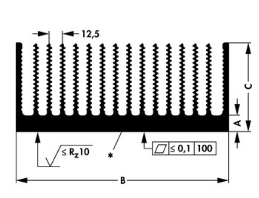
For SK531 A=15mm, B=300mm, C=84mm.
In the catalogue, correlation graph between Rt and the length is presented. We need Rt not more than 0,257 °C/W, this is why we choose the heat sink length (height along, perpendicularly to the ground level) of 140 mm. Thus, the dimensions of a heat sink will be 300x140x84 mm.
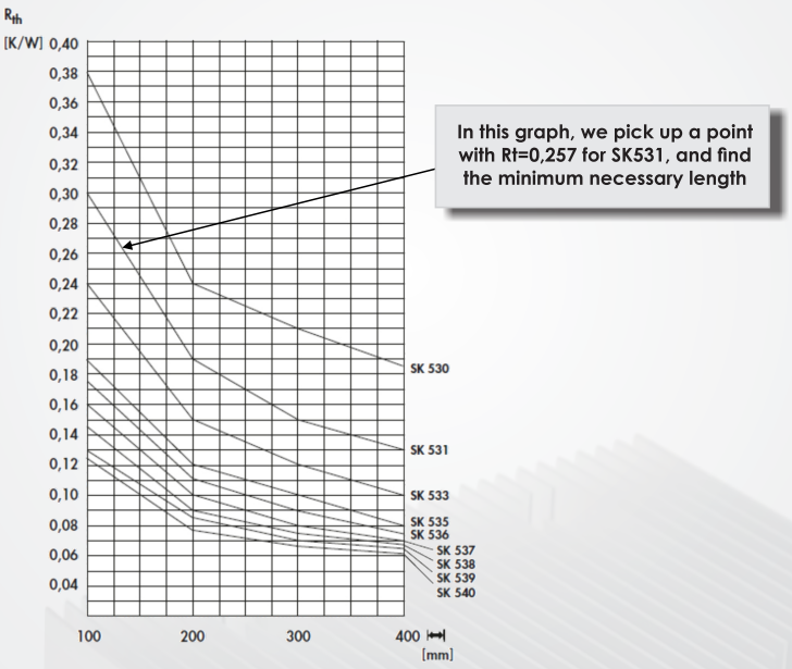
The graphs above (Rt decline with respect to the heat sink’s length for SK53x, it is well demonstrated that the thermal resistance of a heat sink does not depend only on the area of its ribs. Let us consider the example of a heat sink with dimensions 200*400 mm. On the basis of SK530 heat sink, this heat sink is 200 mm wide and 400 mm long, with ribs along the long side, the total number of ribs is 16 (edge ones included). Its Rt per graph is 0,185°C/W. Second variant on the basis of SK533, 400 mm wide and 200 mm long, with ribs along the short side, the total number of ribs is 32 (edge ones included). Its Rt per graph is 0,15°C/W.
In these two examples with the same area of the ribs, Rt of a heat sink 400×200 on the basis SK533, is 1,23 times less than that of a heat sink 200*400 on the basis of SK533! The reason is that with increase of the length of the ribs, the cooling efficiency decreases, which demonstrates the non-linear nature of the graphs.
In its technical recommendations, FISHER Elektronik points out that when referring to the catalogue, the values of Rt, indicated there are true only provided that the heat sink is placed with a vertical layout of its ribs alongside the upward air flow direction with the natural air cooling. If the heat sink is turned upside down (with the ribs being up), the Rt decreases by 10-20%. Given values are calculated provided that the surface is anodized, otherwise (if the surface is not anodized), the Rt decreases by 15% approximately.
Rt values for heat sinks are given for those cases, when the dimensions of a heat sink base do not exceed the dimensions of a heat source (module) by more than 120…130%. With the growth of the dimensions of a heat sink, its efficiency starts to decrease.
Should the heat sink dimensions be too big after Rt calculation and following heat sink selection for the case of natural (without fan) convection, it is necessary to apply forced air cooling by means of a fan. It will help to reduce the dimensions of a heat sink dramatically. Correlation between Rt of a heat sink and air speed (for forced air-cooling) is defined as:
Rtfan = a*Rt (3)
| where: | Rt – thermal resistance of a heat sink for natural convection; |
| Rtfan – thermal resistance of a heat sink for forced convection with a fan; | |
| a – Rt decrease coefficient depending upon air speed. |
This correlation is presented in the graph below:

Special feature of the forced air cooling is that it does not require vertical orientation of the ribs of a heat sink.
There is an Efficiency value present in the calculations (2). In the datasheets, they are given for 100% load at nominal input voltage. In real practice, as a rule, load less than 100%, and used input voltage may differ from the nominal one. Which is why for correct calculation of Rt, we recommend using measured efficiency for real operation conditions. In case when it is impossible to measure the efficiency by the customer, we may assist in providing necessary consulting.
In datasheets, case thermal resistance parameter is provided – environment without a heat sink. If (as a result of the minimum necessary Rt calculation – (1), (2)) the estimated value is more than the value of Rt case-ambient temperature without a heat sink, then it is not necessary to use a heat sink. In such cases, when using power supplies (with output power of 80W and more) without a heat sink, it is necessary to place thermo-evening frame plate with the same dimensions as the module.
Part of heat, dissipated by power supply, is dissipated into the air by other elements of its construction, which have no contact with the heat sink. For example, such elements as side panels, cover and output terminals. In a number of cases, these elements can dissipate quite a major part of produced heat and perform substantial adjustments into calculation of the minimum required thermal resistance of the heat sink, especially for loads less than 100%. Approximately, thermal resistance of of the module elements, not connected with a heat sink, by four times exceeds Rt case-ambient temperature (given in datasheet).
Then resultant value of Rt module+heat sink will be equal to the parallel combination of these resistance values (as per rule of parallel combination of resistance values). Therefore, for JETA 1200, considered above, thermal resistance case-ambient temperature without a heat sink equals to 1,2°C/W. When using a heat sink with Rt = 0,257°C/W, total thermal resistance will be:
Rto = Rt II 4*Rtm = Rt*4 Rtm / (Rt + 4*Rtm) = 0,244°C/W (4)
| where: | Rto – total thermal resistance case + heat sink; |
| Rt – thermal resistance of a heat sink; | |
| Rtm – thermal resistance case-ambient temperature without a heat sink. |
Comparing these two values, it is possible to conclude that consideration of thermal resistance of other elements allowed decreasing thermal resistance by 5%. For loads dramatically less than 100% for this module or other modules with output power a lot less than 1000W, consideration of case thermal resistance can make a significant correction to the thermal correction of a heat sink. It is sufficient to perform calculations as per given formulas (1)…(4).
For MIL-STD-461 compliance, it’s imperative to consider the thermal performance of the heat sink in conjunction with electromagnetic interference (EMI) standards. Efficient dissipation of heat helps maintain system stability and prevents EMI issues arising from excessive temperatures.
Similarly, MIL-STD-704 outlines stringent requirements for aircraft power systems, necessitating careful selection of heat sinks to ensure optimal thermal management and compatibility with aircraft power supplies.
When selecting heat sinks for MIL-PRF-38534 compliant systems, it’s essential to factor in thermal resistance calculations to guarantee compliance with military performance and reliability standards.
To optimize Size, Weight, and Power-Cost (SWaP-C) considerations in military applications, heat sink design must strike a balance between thermal performance and space constraints. Efficient heat dissipation is paramount while minimizing the footprint and weight of the heat sink.
For MIL-COTS (Military Commercial Off-The-Shelf) applications, the chosen heat sink must meet military standards while offering cost-effective solutions. Thermal resistance calculations ensure that the heat sink efficiently manages heat dissipation in military-grade power supplies and other electronic components.
Overall, meticulous attention to thermal resistance calculations and adherence to military standards such as MIL-STD-461, MIL-STD-704, MIL-PRF-38534, and MIL-COTS guidelines are essential in selecting and designing heat sinks for demanding military and aerospace applications.
These recommendations allow performing calculations and choosing a heat sink properly. But it is definitely necessary to perform practical test in real operating conditions to prevent overheating as there are many various factors, which are impossible to consider. It gains special importance for application of power supplies as a part of any other equipment, when total heating and air circulation can greatly differ depending upon certain applications.

