Observing nearly any circuit employed in power supply applications reveals the presence of capacitors positioned at the load’s power supply output. A frequent inquiry directed at power supply providers pertains to the necessity of output capacitors in a power supply and the methodology behind their selection. We’ll delve into both aspects of this inquiry within this discourse.
A rudimentary perspective of a power transmission system involves a power supply, a load, and conductors linking the power supply’s output to the load. In most instances, what we commonly term a ‘power supply’ equates to a voltage supply. Essentially, it delivers a consistent voltage to the load, scaling up to its maximum rated power capacity. Though we’ll use ‘power supply’ and ‘voltage supply’ interchangeably, it’s crucial to grasp that, in this discussion, we focus on a voltage supply.
Upon meticulous examination, it becomes apparent that the power supply endeavors to furnish an unwavering voltage to the load. However, alterations in load current induce fluctuations in the voltage supplied to the load. These variations emanate from shifts in the output voltage directly at the power supply and voltage decline along the conductors linking the power supply to the load.
Fig. 1 – Simplified power delivery circuit
In numerous configurations, the principal shifts in the supply’s output voltage, spurred by variations in load current, stem from the power supply’s bandwidth and the parasitic impedances of the conductors bridging the power supply and the load. Before delving into the compensatory role of bypass capacitors, let’s briefly explore these attributes.
The architecture of power supplies involves comparing the actual output voltage with a reference voltage internal to the power supply. Subsequently, the commanded output voltage undergoes adjustments to minimize the disparity between the attained voltage and the desired voltage.
Fig.2 – Power supply control loop block diagram
In the realm of power supply architecture, the feedback loop imparts a specific bandwidth to the power supply response, contingent on the system’s parameters. Given that most power supplies adopt a switching configuration, the bandwidth is inherently confined to approximately one-tenth to one-quarter of the switching frequency. Assuming a prevalent switching frequency range of 30 kHz to 300 kHz in most switching power supplies, the resultant bandwidth typically falls between 3 kHz (30 kHz/10) and 75 kHz (300 kHz/4). For the sake of this discourse, we’ll consider a 10 kHz bandwidth for the power supply.
The 10% to 90% rise time of a singular pole system can be estimated as Tr = 0.35/BW, where Tr represents the 10% to 90% rise time in seconds, and BW denotes the bandwidth of the system in Hertz. Consequently, a system with a 10 kHz bandwidth would exhibit a rise time of 35 µs (Tr = 0.35/104 = 35 µs). This rise time essentially signifies how swiftly the power supply responds to a step change in load current.
In scenarios of an augmented load current, the voltage at the load experiences a droop while the power supply adjusts to fulfill the new demand. Conversely, if the load current diminishes abruptly, the voltage at the load undergoes a surge as the power supply adapts to meet the altered current demand.
Capacitors strategically positioned at the load serve as reservoirs, absorbing the disparity between the transient load current and the current supplied by the voltage source. Harking back to fundamental electronics, equation elucidates the correlation among current, capacitance, and voltage changes over time. This equation also lends itself to rearrangement for determining either the voltage fluctuation induced by a current change with a known capacitance or the requisite capacitance to curtail voltage fluctuation caused by a shift in current.
I = C * dV/dt
As an illustration, consider a scenario with a 10 kHz bandwidth. If the imperative is to maintain the output voltage within a 120 mV range of the nominal output, and the fluctuation in output current stands at 2 A, the essential capacitance mandated at the load would amount to 583 µF.
C = I * dt / dv = 2A * 35µs / 0.12V = 583µF
Inherent in the conduits linking the power supply and the load are parasitic elements of resistance and inductance, as depicted in figure 3. These parasitic elements, characterized by resistance (Rp) and inductance (Lp), contribute to fluctuations in the voltage supplied to the load corresponding to alterations in the load current. The voltage at the load (Vload) manifests as the supply voltage (Vsupply), diminished by the product of parasitic resistance (Rp) and load current (I). Additionally, it undergoes a reduction influenced by the product of parasitic inductance (Lp) and the rate of change of load current over time (dI/dt), as expressed in equation.
Vload = Vsupply – (Rp * I) – (Lp * dI / dt)
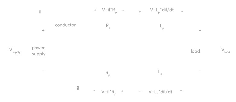
Fig.3 – Power delivery circuit with the conductor’s parasitic resistance and inductance included
The challenge lies in the complexity of computing voltage fluctuations induced by a load transient and the parasitic impedance of power delivery conduits. This intricacy arises from the reliance on both the alteration in load current and the rate at which this change occurs. On a brighter note, specifying power delivery conductors with minimal parasitic resistance and inductance proves to be a relatively straightforward task.
Achieving low parasitic resistance involves employing expansive conductive surfaces, such as robust-diameter wires or broad PCB traces. Meanwhile, curbing parasitic inductance is attainable by minimizing the loop area between the two power conductors. Standard techniques for diminishing the loop area include bundling cables tightly, intertwining two conductors, keeping PCB traces in close proximity, and situating a power trace above a ground plane.
Earlier sections have delved into determining the optimal capacitance at the load to mitigate voltage deviations to a specific threshold. However, an equally pertinent consideration involves the selection of capacitor types suitable for the load. Primary among the criteria for this choice is the requisite capacitance.
When dealing with capacitance needs in the range of ones or tens of microfarads, tantalum or electrolytic capacitors often emerge as the preferred technologies. These capacitor variants boast a reasonable compactness and affordability. On the other hand, for capacitance requirements below tens of microfarads, ceramic capacitors frequently take precedence due to their more compact size and cost-effectiveness in such ranges. It’s crucial to acknowledge that the capacitance value of numerous ceramic capacitors experiences a significant reduction when a DC voltage nears the capacitor’s voltage rating. A web search can yield more information on this particular aspect.
Beyond considerations of size and cost, the values of parasitic inductance and resistance in a capacitor can influence the technology chosen for capacitors. The internal conductors within a capacitor carry inherent resistance and inductance, impacting the overall performance of the capacitor.
Fig.4 – Capacitor impedance vs frequency graph and schematic model including ESR and ESL
A straightforward graph illustrating the impedance of the capacitor model unveils a distinctive behavior pattern. At lower frequencies, the capacitor value predominantly dictates the behavior, shifting to the dominance of Equivalent Series Inductance (ESL) at higher frequencies, and transitioning to the reign of Equivalent Series Resistance (ESR) near the resonant frequency of C and ESL values (refer to figure 4). While the conversation earlier touched upon the requisite capacitance value, it becomes evident from scrutinizing the impedance graph that ESL and ESR play pivotal roles in determining the efficacy of capacitance at higher frequencies.
Inherent to their design, electrolytic capacitors exhibit higher ESL and ESR values, while tantalum capacitors manifest lower values of ESL and ESR. Ceramic capacitors, in turn, boast the lowest values of ESL and ESR. Strategically placing capacitors in parallel proves beneficial in augmenting the C value and mitigating ESL and ESR. The utilization of capacitors employing distinct construction technologies, when amalgamated in parallel, not only diminishes impedance but also diffuses the impedance effects across a broader frequency spectrum.
Fig.5 – Impedance vs frequency of different parallel capacitors and similar parallel capacitors
The strategic amalgamation of smaller-value ceramic capacitors in parallel with larger-value electrolytic capacitors proves efficacious in addressing distinct energy and frequency challenges. Electrolytic capacitors effectively tackle higher energy and lower frequency concerns, while ceramic capacitors come into play for managing higher frequency transients. The ceramic capacitors, owing to the lower energy in transients at higher frequencies, can possess significantly smaller values compared to their electrolytic counterparts.
Building on our discourse, it is now apparent that capacitors are commonly deployed across power supply terminals at the load to alleviate voltage excursions induced by load current transients and the finite bandwidth response of the power supply. The choice of capacitor, both in terms of value and type, hinges on factors such as the power supply bandwidth, the magnitude of load transients, the frequency components of these transients, and the permissible level of voltage excursion triggered by load transients. For further insights and assistance on these matters, reaching out to the technical support team at power supply vendors like Alexander Electric is recommended.

