“The best source of secondary power supply is the absence of it at all”
(the system guys joke)
Advertising of DC-DC secondary power supply converter modules is very noticeable on the general background of electronic components. The authors of advertisements promise to solve almost all power supply problems by using DC-DC modules, citing a mysterious and very impressive thousand watts per cubic decimeter. The cost of such modules is noticeably higher than the cost of conventional components – a resistor, capacitor, comparator or a typical microprocessor.
So what is a DC-DC module? Is it an electronic component or an electronic system in the form of a complete unit or radioelectronic device? Based on his experience as Chief Designer of the company “Alexander Electric” the author tries to answer the fundamental questions related to DC-DC converter modules. First of all such:
(I must honestly note that the author knows the answers to these questions in advance, and suspects such knowledge in some other people as well, but has ambitious plans to tell about the modules without the boring formulas, on the fingers, while keeping the intrigue).
The primary source of electricity, be it a disposable chemical battery, a battery, rectified AC mains voltage, the output voltage of an electromechanical generator, or a solar panel, is generally unsuitable for high-quality powering of numerous circuits and devices of radioelectronic equipment. It is necessary to improve the quality of the primary electricity – to make the voltage stable, reduce ripple, get the necessary voltage ratings, ensure galvanic isolation, prevent the penetration of damaging surges and interference into the equipment, etc. For this purpose, when building a power supply system, secondary power supplies (SPS) are used – stabilized voltage converters – converter devices, without which no secondary power supply can do without. This type of devices includes modules that convert with galvanic isolation of DC voltage of one rating into DC voltage of another rating, i.e. DC-DC converter modules. Hereinafter, for the sake of brevity, we will call these wonderful devices simply and modestly – modules.
As a powerful system components with a large heat generation, the SPS have significantly less reliability than other functional devices of radioelectronic equipment. Along with semiconductors and microcircuits, they use very inconvenient elements for constructive layout – high-rise transformers and chokes, electrolytic and ceramic capacitors, powerful transistors and diodes, as well as heat sinks, output elements of powerful inputs and outputs. All this explains the sad fact that power supplies take up to 30…40% of the total volume and weight of radioelectronic equipment and, in fact, determine the entire reliability of the equipment.
Usually, hardware designers have to solve the very difficult problem of building an optimal SPS for a particular system at the end of overall design, when after the development of all the necessary functional devices become clear requirements for the power supply system, but all the time allocated for the design, as a rule, are out.
Theoretically, a specialized SPS designed for a particular apparatus is always the best and optimal in terms of material intensity, specific performance, electrical characteristics. However, this is true only for a given apparatus when the design time is close to infinity. Realistically in life, after some, often small time, the market demands the birth of new hardware, and everything starts all over again. Significant capital expenditures on research, special apparatuses are required. Highly qualified specialists are needed. Then there is the torment of putting it into production, endless adjustments, a lot of time spent. All this for the sake of a small, as a rule, batch of produced equipment. Economically justified is such a way of development, introduction and manufacture of a single piece of equipment (for example, due to its uniqueness and high cost) or on the contrary, when the equipment for mass production, such as a TV set or a tape recorder, is in demand.
In all other cases, and the vast majority of them, tight design deadlines and quick turnover of equipment are extremely important. Then it is advantageous to use off-the-shelf unified power supply modules purchased from specialized companies that produce such modules in large batches.
Here the famous principle of aggregation, which is widely and successfully used in mechanical engineering and not only. Otherwise, imagine a car (Mercedes-Benz!), in which some unit, for example, power generator, is uniquely “drawn” into a specific configuration of a particular model of the body, forming with it an inseparable whole. That is, a kind of “generator-body” is created. With all the technical benefits of this economy and the time required for design make this situation unrealistic even for an expensive unit, as a result a unified generator in the form of a separate unit, produced by a specialized company (Bosch) is used.
It is useful to be clear about the most important pros and cons of using units. As for any technical device, both bowls of scales turn out to be quite weighty.
The disadvantages includes:
If you are not frightened by the disadvantages, consider the pros. These include:
The listed advantages of using modules in many cases (or even more precisely – in many enough cases) offset the noted disadvantages. And, most importantly, the modules help to achieve multiple savings in money and other resources.
DC-DC converter modules are a progressive direction for designers and manufacturers of electronic equipment in the realization of power supply systems in many practical situations.
So you have in your hands a nice flat electronic component labeled as a DC-DC converter. On the outside they look like big integrated circuits. Big in the truest sense of the term, since they can be the size of a small flat brick (or bricks, if you prefer). So what’s inside there?
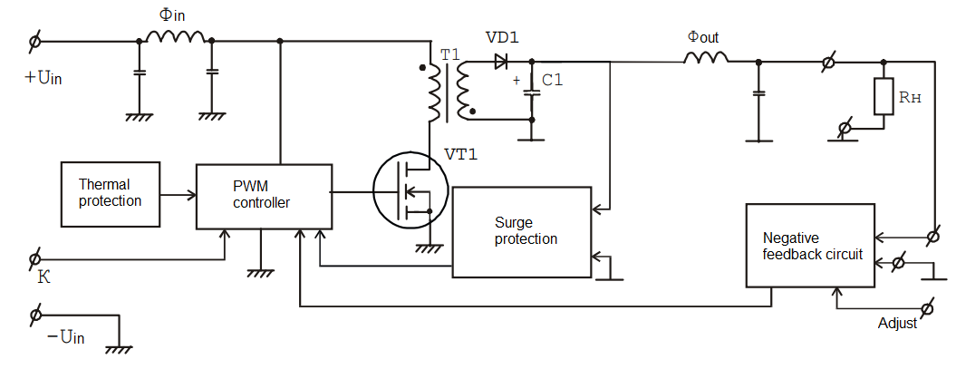
Fig. 1 – Diagram of the flyback converter
If the module has a small output power, 1…5…10W , it is usually based on a flyback converter circuit, (Fig.1).
The power transistor VT1 is periodically opened and closed by the control circuit (PWM controller). During the open state of VT1 in the transformer (multi-winding choke) T1 the energy is stored, which then, in the closed state of VT1 through the rectifier diode VD1 is transferred to the output and charges the capacitor C1. By changing the relative duration of the open state pulses, the control circuit is able to stabilize the output voltage with negative feedback. In general, a closed-loop automatic control system is formed in the stabilized converter, the stability of which is ensured by special methods.
In terms of stability, the most difficult mode for such converters is the no-load mode. Despite the fact that the control circuit in this mode opens the transistor VT1 for a very short time, 50…100 times shorter than the period of switching, in the capacitor C1 accumulates energy, which is nowhere given up. All this leads to an increase in the output voltage above the norm and to a complete shutdown of the converter. After a long enough time the inverter is switched on again. Then the processes are repeated. As a result, low-frequency relaxation takes place, and the output voltage looks like low-frequency pulses. With such a disturbance of stability, often the only solution in practice is to deliberately introduce power losses into the converter to dissipate the excess stored energy. This is usually done with an additional load resistor.
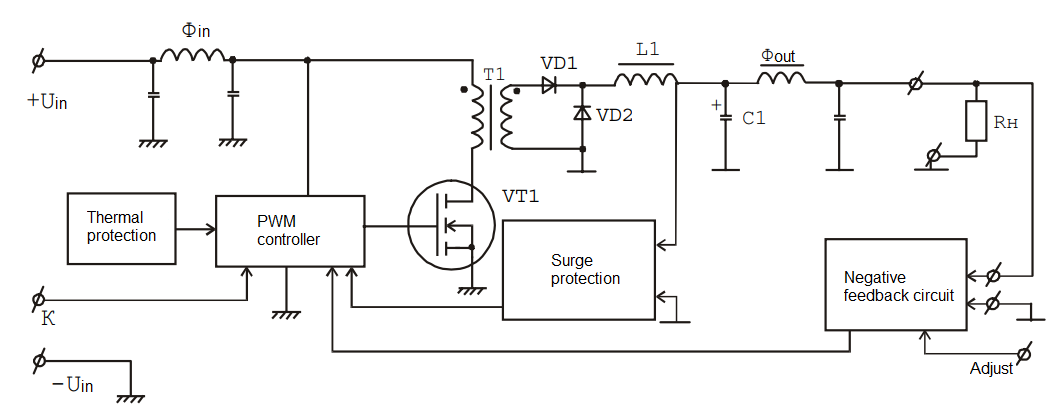
Fig. 2 – Diagram of the forward converter
If your module has an output power of more than 10…15 W, it is usually made according to the scheme of a forward-going converter (Fig. 2).
The power transistor VT1 is periodically opened and closed by the PWM controller. During the open state VT1 through transformer T1 to the output through the rectifier diode VD1 passes the energy, some of which is stored in the choke L1 and the capacitor C1. In the closed state stage VT1 rectifier diode VD1 closes, the energy stored in the choke L1 opens the bypass diode VD2 and is transferred to the output. Here by changing the relative pulse width of the open state the control circuit provides stabilization of the output voltage with the help of feedback. To ensure the stability of the resulting closed-loop automatic control system, special methods are used.
For the direct pass converter the most difficult mode from the point of view of stability is idling. In this case in the choke L1 the mode of discontinuous currents is observed. Choke L1 and the capacitor C1 in this mode cease to play the role of integrator that allocates the average value of pulse voltage at the input of choke L1 and pass into a mode of peak detector. Despite the fact that the control circuit in this mode opens transistor VT1 only for a very short time, the output voltage rises above normal. Then the inverter is switched on again after a sufficiently long time. Then the processes are repeated. The result is a low-frequency relaxation of the output voltage, which is usually suppressed with an additional load resistance.
Transistor optocouplers are used to provide galvanic separation of input and output circuits in the PLA. It should be noted that optocouplers are subject to noticeable aging, and in addition, their characteristics change dramatically with changes in temperature.
The reliability of the op-amp circuit is very important to the modules. Imagine a situation where any element of the module (other than the feedback circuit elements) fails. The module will quietly “die” without causing any damage to the powered equipment. However, the consequences will be catastrophic if one of the elements of the feedback circuit fails. In this case, the module loses the ability to stabilize the output voltage, which increases by 2 – 3 times. As a result, valuable electronic equipment fails due to module failure, the cost of which can be an order of magnitude less than the cost of the equipment. It should be noted that the use of simple output overvoltage protection devices does not often solve this problem, because the energy capabilities of the simplest devices – stabilitron, thyristor, transistor – are negligible compared with the energy of the modules.
Therefore, more expensive (professional) modules use an additional and independent feedback channel, shown in Fig. 1 and 2. The task of the latter is to completely turn off the module for a sufficiently long time when the output voltage is exceeded. From the point of view of reliability, it is as if the feedback channel is redundant. By the way, without such an additional feedback circuit channel, it is very dangerous to use the so-called remote feedback, an accidental breakage of which may lead to the above-mentioned troubles.
Usually the feedback circuit is connected to the output inside the module design. In this case, the voltage at the outputs of the module is stabilized. At the same time, the load of the module may be remote from the module. In this case, due to the fall on the wires, the voltage at the load may be very different from the output voltage of the module and be unstable. Therefore, a number of modules use remote feedback, i.e. there are two additional feedback pins.
In addition, many other service systems are used in the modules. For example, such necessary as command inputs and outputs, as output voltage adjustment, etc. Due to the limited volume of the article, we will not consider them. However, the most important of the service systems are high-frequency filters and thermal protection.
Additional devices, which must necessarily be inside the modules, are input and output high-frequency filters Fin and Foont (Fig. 1, 2). They can be made by the simplest second-order LC circuits, as shown in the figure, or be quite complex. The main thing – if there are no filters in the modules you bought, you should not be happy about the small size of such (often useless!) modules. Filters must be purchased! You understand yourself – the firm that has foisted on you a reduced size modules, will kindly recommend to buy additional modules-filters from it.
About thermal protection. Modules must be universal, structurally suitable for most applications. This is achieved if the module can be used with any cooling system, it will be possible to “fit” in the structural volume of any configuration. Therefore, the module requires very small dimensions and pronounced flatness – a low profile. The price of achieving such miniaturization is a significant concentration of heat released in the module volume. Providing an acceptable thermal mode and, as a consequence, increasing reliability, the heat can be removed from the module. This is done, for example, by means of a heat sink and – further – by conduction, convection or forced cooling, liquid or air. In general, there are a lot of options for cooling systems of modules, which is why the module manufacturers do not regulate the ambient temperature for them, but the temperature of the enclosure! In this situation it is extremely important not to allow obstacles in the way of heat removal from the module, for example, air gaps (we are talking only about tens of microns!) between the module and the heat sink.
As a result, thermal protection inside the module in most cases is the only way to detect a poorly connected module to the heat sink, especially if there are many of them in the system. The protection will simply start shutting down the “sick” overheated module already at the stage of preliminary climatic testing of the hardware and will save not only the module, but also the reputation of the manufacturer and supplier of the hardware – the rubbish will not be taken out of the house.
Thus, converter module is at least a small electronic system, a device that contains from 50…100 to 200…400 electronic components. At the same time, due to its functional and constructive completeness, due to its very wide application, due to its versatility the converter module itself is a complete electronic component, often mounted on a printed circuit board, together with other components that make up the functional units and – further – the complete system in radio electronic equipment.
Structurally, modules come in enclosed and unenclosed form. Their design is based on a printed circuit board, on which the frameless and microframe components are placed. Typically, these are surface-mount components – resistive and capacitor chips, low-power diodes, transistors and microcircuits in microcases, power transistors and diodes in surface-mount packages, and finally, winding elements – transformers, inductors, having a form of flat structures of various designs.
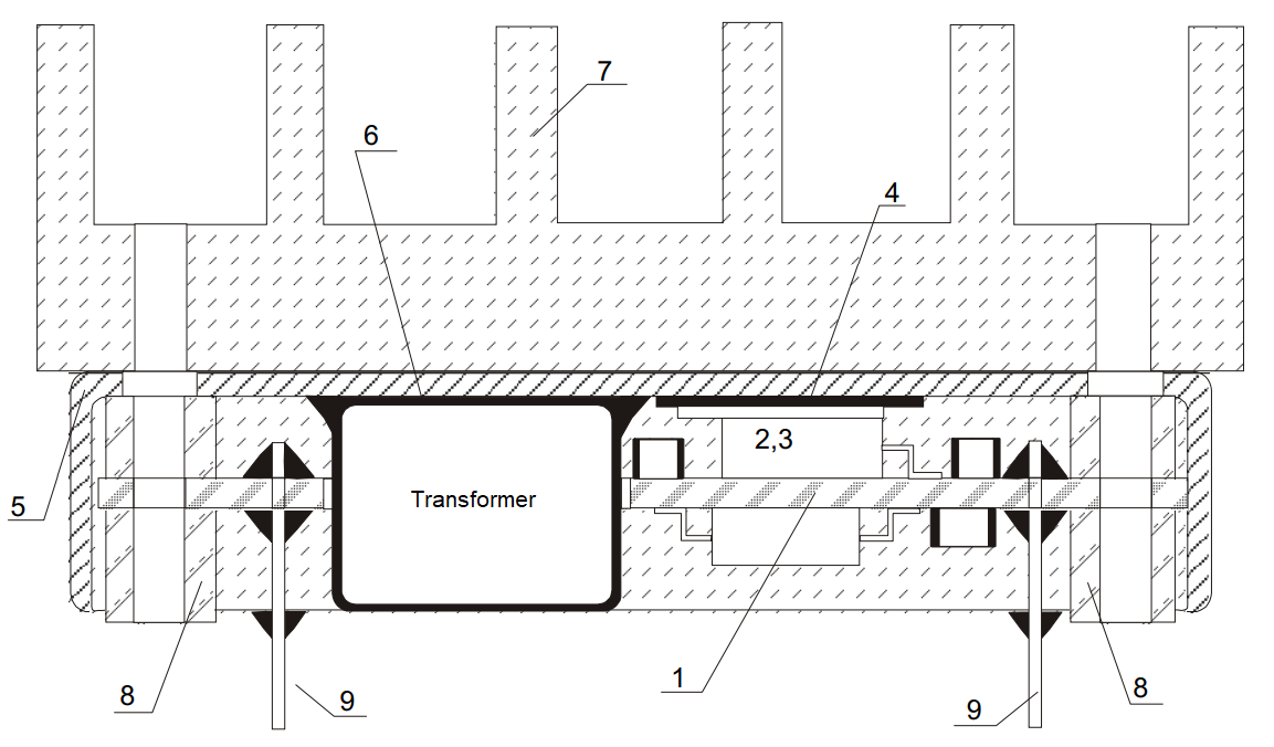
Fig. 3 – Power supply module dimension scheme
In cased modules the printed circuit board is placed in a plastic (for low-power modules) or metal housing and is filled with a special compound with high thermal conductivity. An example of this design can be an old-series module MIRAGE. These modules are produced by “Alexander Electric” (fig. 3). Powerful components with high heat emission, such as power MOSFET (2), a rectifier diode (3) are placed on the printed circuit board (1) through elastic insulating pads with good heat transfer (4) are pressed to the inner surface of the aluminum housing – cover (5). The transformer and the output choke, also generating heat, are close to the surface of the case and are filled with a special high heat conducting compound (6). This allows the heat generated by the transformer and the choke to be transferred to the surface of the housing in a path with minimal thermal resistance. The overall encapsulation of the components in the enclosure is made with a resilient compound of boron nitride, aluminum oxide, etc. It protects all the components of the module from moisture from vibration and shock, and transfers the heat generated in the components to the surface of the enclosure. Silicone compounds used for such purposes are elastic in the temperature range of -60°C … +200°C and more! This is necessary to eliminate the effects on the internal components of the module of mechanical stresses arising in conventional, for example, epoxy compounds due to large differences in temperature coefficients of expansion of the compound and internal components. Other types of modules have similar designs. As an option, modules that have only local casting areas of the most heat-generating components are used. There are modules with an aluminum or copper base plate – a base plate that simultaneously serves as a printed circuit board with the function of heat transfer. In this case, powerful transistors and diodes are simply soldered to the mounting surfaces of the board, transformers and chokes are glued with heat conducting compound, etc.
Here it is necessary to dwell on the widely advertised open-shell modules lately. Promoters of such modules argue that potting compounds have only one useful property – to hide from the eyes of the outsider of manufacturing defects in installation and assembly. It is also argued that to improve reliability it is better to allow significant overheating of some powerful components – transistors diodes, transformers, chokes and to prevent due to lack of compound (using air gaps) heat transfer from warm components to less warm capacitors, optocouplers, etc.
Such a view seems very controversial for many practical situations, and in some cases – simply erroneous. Indeed, when the modules are blown with a strong laminar air flow for the purpose of cooling due to the formation of local turbulences around the heat-generating components of the module, it is possible to withdraw heat from powerful components separately and not to transfer it to capacitors, optrons and microcircuits.
However, modules, as a rule, are installed on printed circuit boards together with other components of functional devices, so the air flow reaching the modules already has significant turbulence, and the above effect is greatly leveled. In addition, in most cases, this flow has a high enough temperature to further increase the thermal stress of the powerful components of the modules, as fans often draw heat flow from the hardware at a much higher power than the heat flow of the modules themselves. Imagine that all the output power of e.g. 600W is dissipated in the internal volume of the hardware itself, 60W is released in the modules and the fans have to draw all 660W of thermal power from the hardware. Dust and dirt further exacerbate these problems, remember how the power supply components and fan blades in your personal computer’s power supply look after 1-2 years of use.
It is also necessary to remember that almost all components of the modules are either bare-body – resistors, capacitors, or micro-body – microcircuits, semiconductors, i.e. having lightweight plastic housings, designed to work only in sealed and moisture-protected volumes. Therefore, in serious applications, you can’t do without casting or a complex sealed enclosure. But what about vibrations, shocks? In powerful modules components are used with relatively high weight, in this case the compound solves the problems of mechanical strength.
Finally, the view that reliability is increased by reducing the temperature of low-power components while deliberately overheating powerful components is quite paradoxical. We can remember that powerful components have an order of magnitude higher failure rate than low-power components.
Certainly, what can be agreed upon is that at low humidity, under comfortable temperature conditions, in the absence of mechanical influences and in the presence of a laminar flow of clean, dust-free cooling air, the use of houseless modules is a very economical solution.
To tighten the module enclosure base (“back” cover) to the heat sink (7), as well as for additional fastening of the module smooth or threaded bushings (8) are used, which are usually placed in the corners of the module (Fig. 3). Module outputs are usually powerful pins (9), designed for transmitting of units and tens of amperes. They are either soldered into the hardware circuit board (not shown in the figure) for electrical connection of the module to the input network and to the load, or the wires of the bulk mounting are soldered to them. With a sufficient number of pins they serve as a reliable element of fixing the whole module to the hardware PCB, and through them part of the heat dissipated by the module is removed into mounting pads on the hardware PCB or into copper strands of wires of the bulk mounting. Sometimes copper bars are used instead of pins in especially powerful modules.

