This paper describes a small discovery made by the author with the direct support and assistance of Y.I. Konev, to whose memory this article is dedicated. I should immediately stipulate that the concept of scientific discovery in this case is formed by the author and does not claim to public success. It is possible that we are talking about the effect known to someone, but the detailed research was made by the author himself and the practical usefulness is obtained.
Forward converters are the most popular today in the technique of building high-frequency and high efficiency stabilized DC/DC converters with low-voltage output voltages.
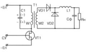
Fig. 1 – Classical forward converter circuit
The classic schematic of a forward converter is shown in Figure 1. It is based on a transistor switch VT1, switched by a sequence of rectangular pulses with constant frequency and duty cycle as a function of output voltage, and a forward diode VD1 and reverse diode VD2 together with a storage choke L1.
In classic papers, the flyback converter is usually discussed in detail. The forward converter is much less fortunate. Usually an obsolete scheme with a demagnetizing recuperation winding is given and it is briefly stated that the characteristic mode of the forward converter transformer is the operation of the magneto wire in one quadrant by a partial hysteresis cycle. It is noted, however, that the efficiency of the forward converter transformer is significantly inferior to two-cycle schemes, where the remagnetization occurs in two quadrants with twice the induction swing.
In the 1980s, when the operating frequencies of transducers increased to hundreds of kilohertz, there was a lot of debate about the advantages and disadvantages of single-cycle and push-pull converters. Zakharov wrote a famous article devoted to comparison of modern high-frequency single-cycle and push-pull converters. The article noted important role of capacitor, connected to primary or secondary winding, in remagnetization of transformer core.
At present, operating frequencies reach 500…700 kHz for the forward converter with a low-voltage input network of 12…24…48 V and 200…300 kHz with a high-voltage input network of 175…400 V. In such cases the demagnetizing winding is practically not used because of design inconveniences, its low efficiency at high frequencies and high level of noise generated by the winding and the recuperation diode. At the same time, the regenerative winding significantly reduces the efficiency (increases the losses) of the transformer.
Let’s look at the operation of a modern classic forward converter circuit without a regenerative winding, widely used by almost all global manufacturers. To explain the essence of the effect we will not overload the consideration with unnecessary details. Let’s assume that the transistor and diodes switch instantaneously, the direct voltage drops on them are zero, the choke and filter capacitor are ideal and have considerable inductance and capacitance respectively, and output voltage ripple can be neglected. Also the input voltage source is stable and has zero impedance.
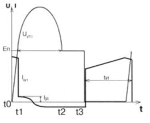
Fig. 2 – Timing diagram of the forward converter operation
Let us denote the magnetizing current of transformer T1 by 1μ and add the parasitic capacitance of the windings to the value of capacitance C1 (see Fig. 1). Let us begin with the time t0 (see Fig. 2), when the power transistor VT1 is off and the current through it instantly falls to zero, and the operating current of the primary winding begins to recharge the capacitance C1, which has an initial voltage EΠ. Since this current is large enough, it quickly recharges the capacitance C1 to a voltage equal to zero, i.e. the voltage at the drain of VT1 becomes equal to the supply voltage (time moment t1) and further recharges the capacitance C1, forming on it the voltage of reverse polarity.
The initial condition for time t1 is a magnetizing current of 1μ flowing in the primary (in this example) winding W1, and continues to recharge capacitor C1 to the polarity shown in brackets in Figure 1. Since in modern converters the windings and capacitors are low-loss elements, i.e. high coefficient of impedance, the parallel resonant circuit Lμ C1 resonates, forming a bell-shaped sinusoidal output at the drain of the power transistor VT1 (see Fig. 2).
The duration of the base of this outlier tocn. = π (Lμ C)1/2, due to the high quality factor of the resonant circuit, the phase shift of current Iμ through the primary winding W1 is -90°. The entire operating current is concentrated in the output choke L1 and disappears in the windings of transformer T1. Of course, the reader understands that this is only possible in multiwinding magnetically coupled inductor coils. From this point on, a free transient process begins in transformer T1, in which the two windings W1 and W2, in this case loaded only by the capacitance C1, are involved.
At the moment t2 the voltage on the secondary winding W2 becomes equal to zero and, trying to change its polarity, by means of the output choke L1, through which an almost constant current flows, it closes the forward diode VD1 and opens the reverse diode VD2. As a result the windings of transformer T1 are short-circuited and from time t2 to time t3 the drain voltage of the transistor remains equal to the voltage EΠ.
This process is characterized by an almost constant current flowing in the winding(s) of the transformer, as the high quality factor of the resonant system of the transformer implies a significant time constant τ = L/r.
Then the power transistor VT1 is opened for time tϰ and then the processes are cyclically repeated.
It is easy to see that at time t1 the magnetizing current of transformer T1 is +Iμ, and at time t2…t3 it is -Iμ. This proves that transformer T1, under these ideal conditions, magnetizes strictly symmetrically in two quadrants in the same way as a push-pull converter transformer with twice the inductance peak.
As a result of this small discovery, ALEXANDER ELECTRIC can use forward converter transformers with nearly full double induction amplitude and not lose anything to push-pull converters at the same frequency.
As far as we know, few people know about this effect and the author would be grateful if any interested researchers would write to him about this effect!

