The most important factor that affects the reliability of power units and, consequently, the reliability of the equipment in which they are installed, is the properly selected thermal mode of their operation. It is known that an increase in the operating temperature of electronic components by 10°С leads to halving their MTBF. Therefore, the choice of the optimal thermal mode of power units in the equipment – one of the first priority measures when building a power system. The purpose of this article is to give consumers of power units an idea of how to remove heat, to teach them to navigate in the curves of unit power reduction, and to reduce the likelihood of mistakes when choosing products from different manufacturers. These errors can be due to the use of different criteria in declaring thermal performance information.
Pulse power units typically have efficiencies of about 75-85%, which results in thermal losses inside the power units of 1/3-1/5 of the power going to the load. If this heat generated by the unit is not removed, it will overheat and fail. There are three heat transfer mechanisms to prevent the units from overheating beyond the values specified in their datasheets:
Heat transfer by emission is carried out by means of electromagnetic waves, which are emitted by bodies heated to a temperature higher than the ambient temperature. This method of heat transfer does not require an intermediate substance, emission is carried out even in a vacuum. The intensity of emission depends on the degree of blackness of the body: objects with a dark surface emit (and absorb) more energy than those with a light surface, so black, matt surface heat sink surfaces are almost always preferable to light and shiny ones. An exception is when there are even more intensely warming elements in the immediate vicinity of the heat sink, then the black heat sink surface will, on the contrary, absorb external emission. Emission heat transfer is usually no more than 1/10th of other heat transfer methods, so as a rule, the calculation of emission can be neglected and it can be assumed that it provides some reserve for the heat sink temperature. If there are no intensively warming elements near the power unit, it is reasonable to apply chemical or galvanic blackening of its heat sink.
Thermal conductivity is a property of a material to transfer heat through its thickness from a hotter surface to a surface with a lower temperature. A measure of the effectiveness of this method of heat transfer is the heat transfer coefficient of a material. The heat transfer coefficient is measured in W/(m*K) or W/(m*°C) and indicates how much heat transfers due to heat transfer per unit of time through the unit of heat transfer surface for a temperature drop of 1 degree per unit of material thickness. Metals have the highest thermal conductivity, gases have the lowest, and the thermal conductivity of a vacuum is zero. In metals, thermal conductivity is mainly due to the movement of free electrons, so the best conductors of electric current are also the best conductors of heat.
Table 1 shows the values of the thermal conductivity coefficient for some materials.
| Material | Сoefficient of thermal conductivity λ, W/(m*K) |
| Silver | 407 |
| Copper | 384 |
| Beryllium oxide (beryllium ceramics) | 200 – 240 |
| Duralumin | 186 |
| Brass | 111 |
| Steel | 47 |
| Mica | 0,43 – 0,6 |
| Air | 0,03 |
| Vacuum | 0 |
Table 1 – Thermal conductivity coefficients some materials
Convection is the transfer of heat in liquids or gases by the flows of the substance itself. There is natural convection, when the lower layers of the substance when heated become lighter and rise to the top, and the upper layers, on the contrary, cool down, become heavier and go down, and forced (forced) convection, when the movement of matter is due to the action of some external forces (fan, pump, etc.).
In order to properly calculate the thermal mode of the power unit, it is necessary first of all to estimate its heat loss in watts. The heat loss power Pdiss can be calculated using the formula:
Pdiss = Pout / η – Pout`
where Pout – output power of the power supply unit, W; η – unit efficiency.
Coefficient of efficiency is non-linear and depends on input and output voltages of the unit, on its rated output power and real power factor and even on the unit’s case temperature.
In calculations we can use approximate efficiency values of 0.75-0.85, considering that maximum efficiency corresponds to the unit’s load factor of about 0.7, output voltage over 15 V and the rated output power over 100 W. Low (up to 5 V) output voltage, operation at minimum or maximum load and small (up to 10 W) rated output power of the units lead to lower efficiency.
In addition to the calculated determination of the power loss, you can get a more accurate experimental value. To do this, you must measure the input and output values of voltage and current in those electrical and temperature modes, in which the unit will be operated in the equipment, and on the difference of input and output power to calculate the power loss. Note that due to the pronounced pulsed nature of current consumption from the AC mains for AC/DC units, measuring the power consumed by the unit can lead to a significant error, so measurements must be made when feeding the AC/DC unit with direct current from a voltage 1.41 times higher than the AC voltage used. All measuring instruments must be resistant to high-frequency pulse interference, voltmeters should be connected directly to the corresponding pins of the unit.
Now the first important conclusion can be made. Selection of a suitable power unit should begin with a careful study of the dependence of its efficiency on the various electrical and temperature conditions of operation. Such reference materials are sure to be provided by the most professional and longest-running manufacturers on the market. Having this information can already be an advantage when choosing the right power supply.
Once you know how much power Pdiss should be removed from the power unit to prevent it from overheating above the limits, you can calculate the maximum thermal resistance of the heat dissipation system. This determines how much hotter the power unit will be than its surroundings:
Rmax = (Tmax – Tamb) / Pdiss
where Tmax is the maximum allowable temperature of the power unit’s case; Tamb is the ambient air temperature during the power unit’s operation (the heat loss of the elements adjacent to the unit must also be taken into consideration).
The obtained value of thermal resistance must first be compared with the thermal resistance „unit case – environment“ Rcase-ambient, the value of which some power unit manufacturers provide in the technical documentation (but, unfortunately, not all of them yet). If Rcase-ambient value is less than the calculated one, an additional heat sink is not required for the unit – the surface area of the unit itself is sufficient for heat removal, if there are no obstacles to free circulation of ambient air.
Table 2 gives typical values of thermal resistance „unit’s case – environment“ Rcase-ambient for power supply units of MDM and MAA series produced by Alexander Electric.
| Dimensinons, mm | Rated input power, W | Thermal resistance Rcase-ambient, °C/W | Heatsink thinckness, mm |
| DC/DC Power Units | |||
| 30×20×10 | 5 | 19,8 | 1,5 |
| 40×30×10 | 7,5 | 12,5 | 2,5 |
| 48×33×10 | 7,5, 10, 15 | 8,7 | 2,5 |
| 58×40×10 | 15, 20, 30 | 7,8 | 2,5 |
| 73×53×13 | 30, 50, 60 | 5,3 | 2,5 |
| 95×68×13 | 60, 100, 120 | 3,3 | 4 |
| 110×84×13 | 120, 160, 200, 240 | 3,0 | 4 |
| AC/DC Power Units | |||
| 107,5×56,5×18,5 | 20 | 6,4 | 4 |
| 129,5×61,5×21,5 | 50 | 4,8 | 4 |
| 136,5×97,5×33 | 100, 150 | 2,7 | 6 |
| 195,5×106,5×40 | 200, 300 | 1,8 | 8 |
| 242,5×132,5×40 | 600 | 1,2 | 8 |
| 284,5×174,5×50,5 | 900 | 0,8 | 8 |
Table 2 – Power units thermal characteristics
It should be noted that the value of thermal resistance of various structures, including metal housings of power units, depends, and not linearly, on many factors. It depends on the location of the structure in space (how easy the free or forced transfer of heat into the environment is), the value of dissipated power, the ambient temperature, and the temperature difference between the environment and the power unit enclosure. However, within the assumptions of power unit thermal design, the Rcase-ambient thermal resistance value can be considered constant.
Manufacturers of electronic equipment often provide in technical information only a limitation on the maximum temperature of the device housing, briefly and most accurately describing the requirements for the thermal conditions of the product. In this case, the difficulty of ensuring the necessary operating conditions is left to the consumer. Therefore, first of all, of interest are those companies that provide so-called typical curves of maximum output power reduction of units without additional heat dissipation depending on the ambient temperature („thermal curves“, or Derating curves). The horizontal axis shows the ambient temperature and the vertical axis shows the maximum power output of the power supply unit at which the case temperature will not exceed its limit. The horizontal part of the thermal curve corresponds to the maximum long-term power of the power unit, and the unit’s case temperature in this part has approximately the same superheat ΔT relative to the ambient temperature Tamb, equal to
ΔT = Rcase-ambient * Pdiss
The descending part of the thermal curve in the area of higher ambient temperatures is characterized by the same case temperature, equal to Tmax. This is the second important point to consider when analyzing the thermal performance of power units. Strictly speaking, the descending part of the thermal curve, due to the nonlinear characteristics of the unit’s efficiency and thermal resistance, should have a nonlinear form, close in shape to a parabolic segment. However, within the limits of the selected errors, most power unit manufacturers replace the nonlinear decrease in output power with one or more linear sections.
The next, third, very important aspect is to understand the meaning of the point on the temperature axis to which the descending part of the thermal curve (zero power point) tends. The value of this temperature can be used to assess the level of the element base used and the complexity of the applied technology, as well as to identify obvious errors made by a poor approach to the study of thermal modes of manufactured products.
The element base used for the production of switching power units can be divided into four groups, differing in achieved electrical parameters, cost of implementation and reliability.
Accordingly, the power supply units price category Commercial, built on the basis of electronic components of similar purpose, should have a point of zero power, directly related to the limited operating temperature of the circuit components, ie no more than +70 … 85 ° C, category Professional – to +85 … 105 ° C, Military – to +105 … 130 ° C and Special – to +150 ° C.
Here we come to the fourth important conclusion. The point of zero power of the power unit, which does not correspond to the adequate cost of its element base, may indicate an insufficiently high-quality approach of the manufacturer to the calculation of thermal modes of the circuit.
Let’s take a closer look at the physical meaning of the thermal curve on the example of a DC/DC power supply unit MDM10-1V27SU by Alexander Electric with a rated output power of 10 W.
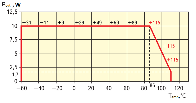
Fig. 1 – Thermal curve of the power unit
The figure shows that in the ambient temperature range from -60 to +86 °С the unit’s case temperature will be within acceptable limits even when working at full load of 10 W. Superheating ΔT of unit enclosure relative to environment temperature for power loss Pdiss = 10 W/0.75 – 10 W = 3.3 W at this section will be equal to ΔT = 8.7°С/W * 3.3 W = 29°С, i.e. at environment temperature of -60°С, the unit enclosure will have temperature of about -31°С, and at environment temperature +86°С – about 115°С. With further increase in ambient temperature, the unit’s housing temperature will exceed the limit value of +115 °С. To prevent this from happening, either an additional heat sink is required while maintaining the load power of 10 W, or a reduction in the output power. Decreasing part of the thermal curve corresponds to the unit’s case temperature +115°C, at maximum ambient temperature +110°C the maximum output power of the unit will be 1.7 W. The area bounded by the heat curve is the area of acceptable power unit operation without the use of a heat sink, provided there is free circulation of ambient air. Here it should be recalled that to improve the reliability of the power supply system, it is recommended that the unit be operated with a power factor of no more than 0.7 and that long periods of operation at case temperatures close to the maximum allowable temperature be avoided.
If the surface area of the power unit is not sufficient to provide an acceptable case temperature, special heat dissipation measures such as using an additional heat sink or forced airflow should be taken.
The thermal curve can be used to calculate the Rcase-ambient thermal resistance value, taking into account that at the point where the output power decrease starts, the case temperature is equal to the maximum allowable temperature:
Rcase-ambient = (Tmax – Tderating) / Pdiss
where Tderating is the ambient temperature at which the output power decrease begins.
When analyzing thermal curves of power units produced by domestic firms, we sometimes encounter obvious errors. Thus, for example, the thermal calculation given in shows that heat loss of 160 W of MDM160-EP series power unit with an available effective heat transfer surface area of about 105 cm2 and a claimed efficiency of 80% at 160 W of load power will lead to a case temperature of about 390 °C (!) at +105 °C of the environment. At the same time in the catalog and on the website of the same manufacturer states that this power unit is able to operate without reducing power up to +105 °C without additional heat sink, and the temperature of the case will not exceed the limit value of +125 °C. In this case, the temperature of the beginning of the power output decrease without the use of an additional heat sink should be far in the negative temperature region. Wrong data is also indicated by the fact that the falling part of the thermal curves of the MDM10-EP and MDM160-EP power units considered in this article tends to unrealistically high temperatures of +149 °C and +133 °C for the imported element base of category Commercial used in these units.
The choice of heat sink design is usually based on the layout of the power unit in the hardware; very often an acceptable heat sink can be the chassis or the metal wall of the device. As a rough first approximation, the necessary surface area of an aluminum heat sink can be estimated from the following ratio: a power unit would require a 20 cm2 heat sink for each watt of power dissipated, so the minimum square centimeter area of a Sheatsink aluminum heat sink is equal to 35 °C above ambient temperature:
Sheatsink = (20 * 35 * Pdiss) / (Tmax – Tamb)
where Pdiss – heat loss power, W; Tmax – maximum allowable power unit case temperature, °С; Tamb – ambient air temperature, °С.
Let’s calculate, for example, the area of an additional radiator for the operation of the power unit at +100 °C for a load capacity of 7.5 W.
Pdiss = 7,5 W / 0,75 – 7,5 W = 2,5 W
Rmax = (115 – 100 °С) / 2,5 W = 6 °С/W
The available value of thermal resistance Rcase-ambient = 8,7 °С/W exceeds the calculated value, which also confirms the need for a heat sink.
You can use a ready-made heat sink, the thermal resistance of which, paired with the case of the selected unit will not exceed 6 °С/W (data on the thermal resistance are often given in the documentation for the heat sink), or calculate the approximate area of aluminum heat dissipation system by the formula (4):
Sheatsink ≈ (20 * 35 * 2,5) / (115 – 100) = 116 cm2
When making a heat sink in the form of a plate or when using an aluminum hardware wall, the surface area of the power unit involved in the heat exchange with the environment can also be taken into account. In this case, a square aluminum heat sink of approximately seven by seven centimeters, or a section of the hardware wall of a similar area, is sufficient. The thickness of the heat sink plate or the base of the radiator should ensure uniformity of heat distribution over the heat sink. Approximate values of heat sink base thickness are given in Table 2.
When arranging a power unit in the equipment, it is necessary to pay attention to the correct positioning of its heat sink in the space. Natural or forced convection air flow must freely „wash“ the heat sink surface or fins of the heatsink. In this case, the arrangement of heat dissipating surfaces will be more effective, when the heated air flow is diverted as quickly as possible from the place of heat exchange.
You can use the following quick method to determine the thermal performance of the power units you purchase. Under normal climatic conditions, connect the selected unit to a load of about 10% of maximum power. After the thermal equilibrium is established, make sure that the unit housing temperature does not exceed the limit value specified in the technical documentation. Then, by smoothly or step-by-step increasing the unit load, reach the thermal balance at which the temperature of the unit enclosure becomes equal to the maximum permissible temperature. At this point, you can measure the efficiency, calculate the power loss, the value of thermal resistance and compare the obtained values with what you expect and with the manufacturer’s declared characteristics. This simple method will allow you to make a conclusion about the suitability of the power unit for use in hardware without an additional heat sink or will serve as a good basis for experiments with the heat sink.
An additional contribution to the thermal resistance of the heat sink system is made by the power unit-sink transition. To reduce this transient thermal resistance it is necessary to use a special heat conducting paste, paying attention to the area and flatness of the contact between the unit and the heat sink, the uniformity of the paste distribution and its minimum thickness. When using paste or a thermally conductive insulating pad, the additional thermal resistance can be estimated using the following formula:
Rp = δp / (λ * Sp)
here δp – thickness of gasket or paste layer; λ – heat conductivity coefficient, W/(m-K); Sp – adjoining area of gasket or paste layer.
The use of forced convection by means of a fan allows to reduce significantly the size of the heat dissipation system, and in some cases to refuse it altogether. Air flow across a power unit’s heat dissipating surface or heat sink, at a rate of 1m/s (60m/min), nearly halves the heat resistance, effectively doubling the effective heat dissipation area compared to free convection.
When using fans as blower sources, attention should be paid to their MTBF and timely maintenance, especially when operating in dusty environments, as fan jamming can lead to overheating and failure of the power unit.
Another peculiarity of air-cooling systems is the decrease of their efficiency when the altitude above sea level increases or when the atmospheric pressure decreases. For example, already at an altitude of 3,500 m, the efficiency of both natural convective and forced air cooling decreases by 25%.
The difficulty in determining the many parameters that influence heat transfer effects makes thermal calculations difficult and imprecise, but understanding the physics of the processes involved helps to realize the best possible cooling system. Manufacturers of switching power supplies offer ready-made cooling systems most suitable for the products they produce, specialists of professionally prepared firms will certainly answer all your questions, help to avoid many mistakes, quickly analyze various options of heat dissipation in the equipment and choose the best of them, reduce the development time of the cooling system and increase its efficiency by an order of magnitude.

